Chapter 5
How is a circuit described?
- The browser
- The network
- Software and languages
- The CPU
- Memory
- Arithmetic
- Logic gates
- The switch
The CPU of Chapter 5 is the main machine this part set out to build. Now stay on that machine and ask how a circuit too large to draw by hand is written down. The chapters so far have built circuits by writing one gate function that calls another: a full adder calls half adders, which call XOR and AND. That is fine for a handful of gates. The processor of Chapter 5 already has hundreds, and a real one has billions of transistors. Nobody wires those by hand. Instead a circuit is written down as data: a source description, and eventually a list of which gate drives which wire. A hardware description language such as Verilog is the source; a netlist is the gate-and-wire description tools compile from it; and a simulator is how a chip is tested long before it is built in silicon.
5.1 A circuit is a netlist
Strip a circuit to its essentials and it is a graph: gates are nodes, and the wires between them are edges. Writing that graph down gives a netlist: one record per gate, naming the wire it drives, its kind, and the wires it reads. Figure 5.2 draws the netlist for the XOR circuit Chapter 2 built from four NAND gates.
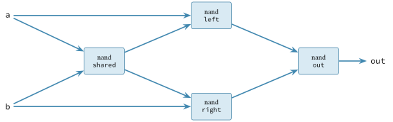
The data is a direct transcription of the drawing.
Example 5-1. The XOR circuit, written as data
# XOR, described as the four-NAND circuit Chapter 2 built by hand.
XOR_FROM_NAND = [
    Gate("shared", "nand", ("a", "b")),1
    Gate("left", "nand", ("a", "shared")),
    Gate("right", "nand", ("b", "shared")),
    Gate("out", "nand", ("left", "right")),
]
- one record is one gate: the wire it drives (shared), its kind (nand), and the two wires it reads (a and b)
5.2 Simulating the description
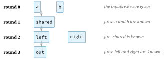
To find what the circuit computes, the simulator works outward from the inputs. A gate can fire only once every wire it reads is known; firing it makes its output wire known, which may let other gates fire. The value spreads in waves until every wire is settled. Because a gate waits on its data, not on its place in the list, the order the gates are written in does not matter.
Example 5-2. Evaluating a netlist
def simulate(netlist: list, inputs: dict) -> dict:
    """Evaluate a combinational netlist. `inputs` gives the input wires' values;
    the result holds every wire's value. A gate fires once all the wires it reads
    are known, so the listing order does not matter."""
    values = dict(inputs)
    pending = list(netlist)
    while pending:
        ready = [g for g in pending if all(w in values for w in g.ins)]1
        if not ready:
            raise ValueError("netlist has an undriven wire or a feedback loop")2
        for gate in ready:
            values[gate.out] = _GATES[gate.kind](*[values[w] for w in gate.ins])3
        pending = [g for g in pending if g not in ready]
    return values
- a gate is ready when every wire it reads already has a value; each round fires all the ready gates at once
- if some gates remain but none are ready, the netlist is not a valid combinational circuit: a wire is undriven, or gates feed back into a loop
- firing a gate computes its wire by calling the very function its kind names, built in the chapters so far
Figure 5.3 shows the waves for the XOR netlist: from the inputs, shared fires, then left and right, then out.
A netlist turns a large circuit into data a tool can inspect. The next chapter keeps the same CPU circuit and makes it faster, not by redrawing it from scratch, but by overlapping the instructions that run through it.
Exercises
- Describe NOR as a netlist of NAND gates, and confirm the simulator agrees with the NOR gate.
- Build a netlist whose output feeds back into its own input, and watch the simulator refuse to run it.